MS MECHANICAL ENGINEERING STUDENT · EIT
Aidan P. Steins
As a mechanical engineer and lifelong tinkerer, I am passionate about applying technical skills, engineering theory, and creativity to solve challenging problems. I have contributed to a variety of projects involving sheet metal design, additive manufacturing, CAE/CAD tools, test development, execution, and analysis. Following a B.S. from the University of San Diego and industry experience in a design role, I am currently pursuing an M.S. at CSU Long Beach after expanding my knowledge through an automotive design internship.
EDUCATION
ACADEMIA, CERTIFICATIONS, AND LICENSES
M.S. Mechanical Engineering
CALIFORNIA STATE UNIVERSITY, LONG BEACH — COLLEGE OF ENGINEERING
Fundamental Coursework
- Design of Experiments
- Advanced Mechanics of Deformable Bodies
- Composite Materials
- Structural Analysis of Composite Laminates
B.S. / B.A. Mechanical Engineering
UNIVERSITY OF SAN DIEGO — SHILEY-MARCOS SCHOOL OF ENGINEERING
Fundamental Coursework
- Design of Machine Elements
- Finite Element Analysis
- Computer Applications in Engineering
- Introduction to Computational Fluid Dynamics
CERTIFICATIONS & LICENSES
CATIA ASSOCIATE: MECHANICAL DESIGNER
3DEXPERIENCE CATIA
CSWP: MECHANICAL DESIGN
SOLIDWORKS
CSWP: ADVANCED SHEET METAL
SOLIDWORKS

ENGINEER-IN-TRAINING (EIT)
LIC. #180969
EXPERIENCE
PROFESSIONAL HISTORY
Lucid Motors
EXTERIOR DESIGN INTERN · NEWARK, CA
- Drove an ECR through OKTC approval by cross-functional teams and stakeholders. Utilized decision matrices for concept selection, CATIA 3DX for CAD implementation and drawing creation (employing GD&T and datum schemes), and supported development of the DFMEA, DVP, and ESOW.
- Developed an ORCA linear motor-controlled testing rig to simulate low-speed straight and angled obstacle impacts with height capabilities ranging from 120 - 300+ mm. Executed multi-thousand-cycle impact tests on exterior aerodynamic components to validate lifetime durability.
- Developed and performed critical DVP testing for sourced products and designed components, including washer fluid cleanability testing, wiper blade life expectancy, and fastener testing of license plate bracketry.
- Toured Lucid’s prototyping and AMP-1 production facilities, gaining critical knowledge of E-Cube use cases, prototype line development, and designing for production line assembly.
Weistec Engineering
MECHANICAL DESIGN ENGINEER · ANAHEIM, CA
- Contributed to the design of an articulating and deployable solar array on a mobile power station, focusing on the conceptual structure design, component sourcing, and actuator calculations while also supporting CAD modeling, documentation, and fabrication.
- Designed and prototyped bent sheet metal and 3D-printed components using SolidWorks sheet metal and surfacing tools, fiber laser cutting, press brake bending, and engineering-grade fiber-reinforced plastics.
- Applied DFMA principles to create robust mechanical parts and modify existing designs, resulting in a substantial reduction in manufacturing time.
- Digitized 40+ automotive components using a five-axis scanner and probe (CMM) for integration purposes, which resulted in significantly faster CAD integration.
- Managed and created part and assembly BOMs and technical drawings, and tracked 75+ design revisions in SolidWorks PDM, ensuring 100% revision control.
- Conducted first article inspections of 15+ outsourced components to confirm dimensionality and fit in the final application, reducing the number of sample iterations and improving client-vendor communication.
PROJECTS
PROFESSIONAL, ACADEMIC, AND PERSONAL
Exterior Component Design, Development, and Testing
Summary
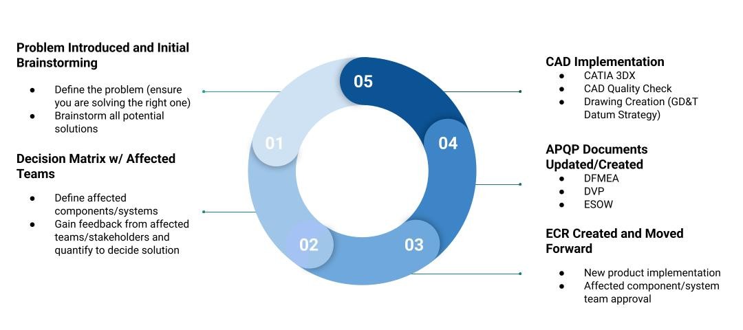
New Component Development – I was given the responsibility of carrying an exterior component from initial design concept generation and selection through ECR approval by all affected teams. The cycle of all related milestones is shown in the first image.
Low-Speed Impact Testing Rig – After hearing from several DREs that testing underbody exterior components against low-speed obstacles (such as parking curbs, barriers, or potholes) was a growing need, I proposed and designed a low-speed impact testing rig. As shown in the second image, using ORCA linear actuators, linear rails, and various hardware alongside CATIA 3DX, custom 3D-printed components, plasma-cut metal, and common shop tools, I developed a testing rig capable of automated cycle control to simulate repeated low-speed impacts of various road obstacles throughout the expected lifetime of the vehicle.
DVP Development and Execution – I contributed to the development of DVPs for several items, including cowl screens, wiper blades and washer fluid, and self-tapping fasteners for license plate bracketry. We performed blind ratings with multiple observers using a numeric wipe rating scale to evaluate the wear rate of wiper blades relative to cowl screen surface roughness. I also helped customize a test plan to quantify the cleanability, freeze point, and chemical resistance of various washer fluid formulations. Additionally, I supported fastener testing of self-tapping fasteners in molded plastic bosses to establish a suitable torque specification for the joint and evaluate serviceability of the component. Shown in the third image is a torque versus angle graph for a thread-forming screw in plastic; statistical analysis across multiple trials then helped identify a safe torque range with high confidence.
Results
New Component Development – Not only did this process aid in meeting the timeline for the program, but it was also a great learning experience in understanding how to work with cross-functional teams and receive feedback from many stakeholders to create a product that meets all expectations and requirements. It also taught me the fundamental process behind product design and development, which is an invaluable skill as an engineer.
Low-Speed Impact Testing Rig – The final testing rig accommodated obstacle heights ranging from 120 to 300+ mm and delivered up to 1,000 N of impact force. Automated controls allowed for programmable stroke lengths and speeds for each impact cycle. This testing rig allows us to simulate thousands of impacts within only a few hours, thus validating the component for the expected lifetime of the vehicle.
DVP Development and Execution – Blind ratings proved that there was a correlation between cowl screen surface roughness and wiper blade wear rate. This in-house testing saved roughly $20,000 in external testing costs while also providing faster feedback to the design team. After qualitatively analyzing the cleanability results of multiple washer fluid formulations, we identified a significant difference between fluids, which provides purchasing executives with valuable information to consider before sourcing. Lastly, testing the self-tapping screws in molded bosses established a quantifiable torque specification for the joint and helped validate the serviceability of the component. Additionally, it taught me the fundamental principles behind self-tapping joint design and fastener theory.
Optimization via Finite Element Analysis of Carbon Fiber Reinforced Polymer Patches by Design of Experiments


Summary
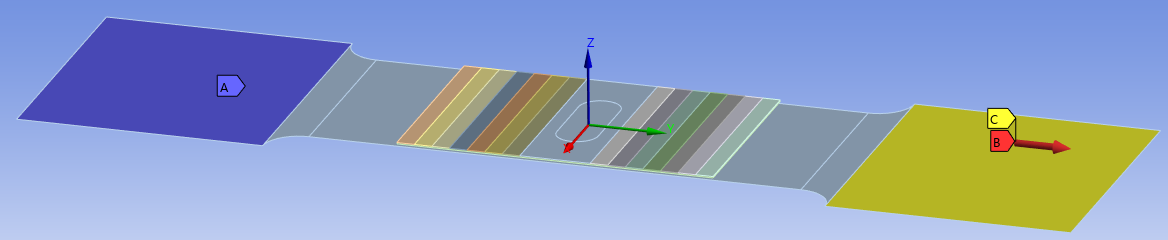
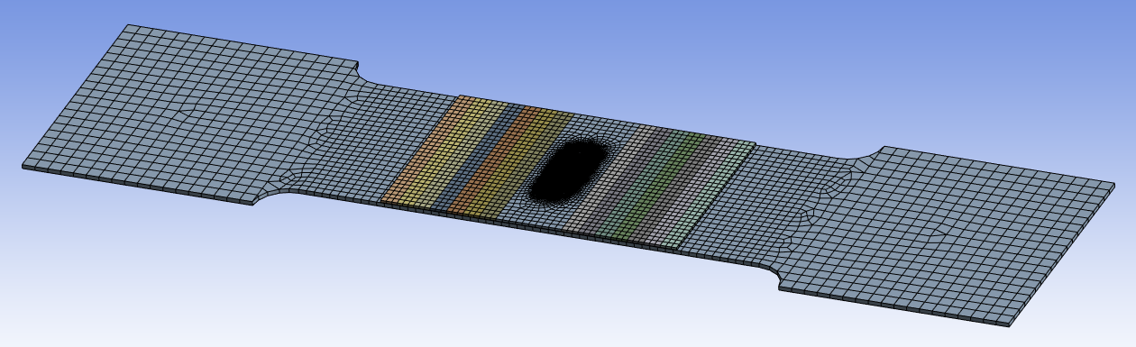
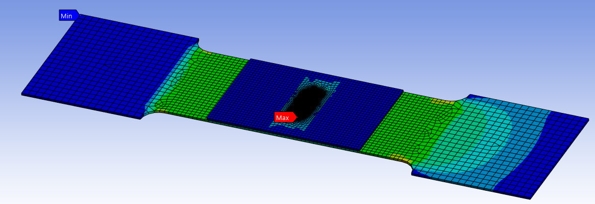
Carbon fiber reinforced polymer (CFRP) patches are widely used across industries to repair cracked metallic and composite structures. Using past experimental research as a guide for our setup and expected results, the goal of this project was to develop a finite element model in ANSYS Mechanical of a pre-cracked metallic dogbone coupon reinforced with a CFRP patch under tensile loading (mimicking an Instron tensile test). We investigated the effect of three parameters—patch shape, number of layers, and adhesive thickness—on the maximum von Mises stress at the crack tip. We developed a full-factorial Design of Experiments (DOE) to minimize the number of trials required to quantify the effect of these three factors on the maximum stress at the crack tip. To avoid complex plastic material behavior, we performed all simulations within the linear elastic region of the involved materials. To minimize element count and computational time, 3D shell elements were used for all bodies in the model. The CFRP patches were modeled using ANSYS's 'Layered Section' feature (as shown in the first image collage) to reduce the number of contact definitions and layers required to model the rectangular, triangular, and inverted triangular patches. Boundary conditions were applied to mimic the grip and loading conditions of a real-world tensile test. Convergence studies were performed on each simulation by refining the mesh at the crack tip using a pre-defined methodology.
Results
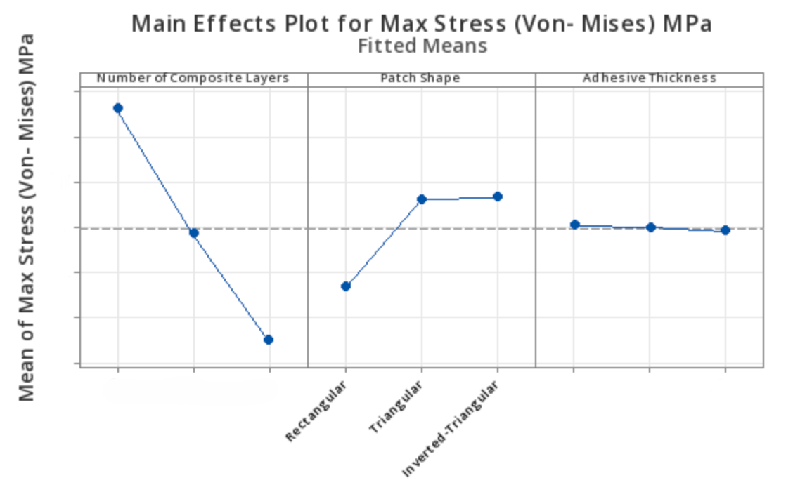
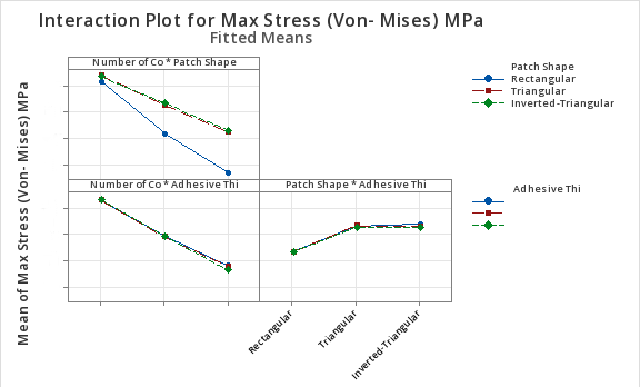
The initial regression model included all main effects, two-way interactions, and three-way interactions; however, doing so left no degrees of freedom for error. After removing the three-way interactions from the model, we were left with the main effects and two-way interaction terms. After reviewing the normal probability and fitted-value plots for this model, we determined that a linear model adequately captured the effects of the three factors on the maximum stress at the crack tip, as confirmed by a high R-squared value. Shown in the second image collage are the main effects and interaction plots using this reduced linear model. We can see that the number of composite layers has the largest effect on maximum stress at the crack tip, followed by patch shape, and lastly adhesive thickness. It is important to note that adhesive thickness may have a more significant impact on maximum stress at the crack tip if more elements were available to model through the thickness of the adhesive layer. The interaction plots show that the interaction between the number of composite layers and patch shape, as well as the interaction between layer count and adhesive thickness, are statistically significant. However, because adhesive thickness alone is statistically insignificant in this model, the interaction between layer count and adhesive thickness is less critical than the interaction between layer count and patch shape. From these conclusions, we created our third and final reduced model, which retained only the statistically significant factors and interactions.
Digital Imaging Technician (DIT) Vehicle and Power Station Trailer
Summary
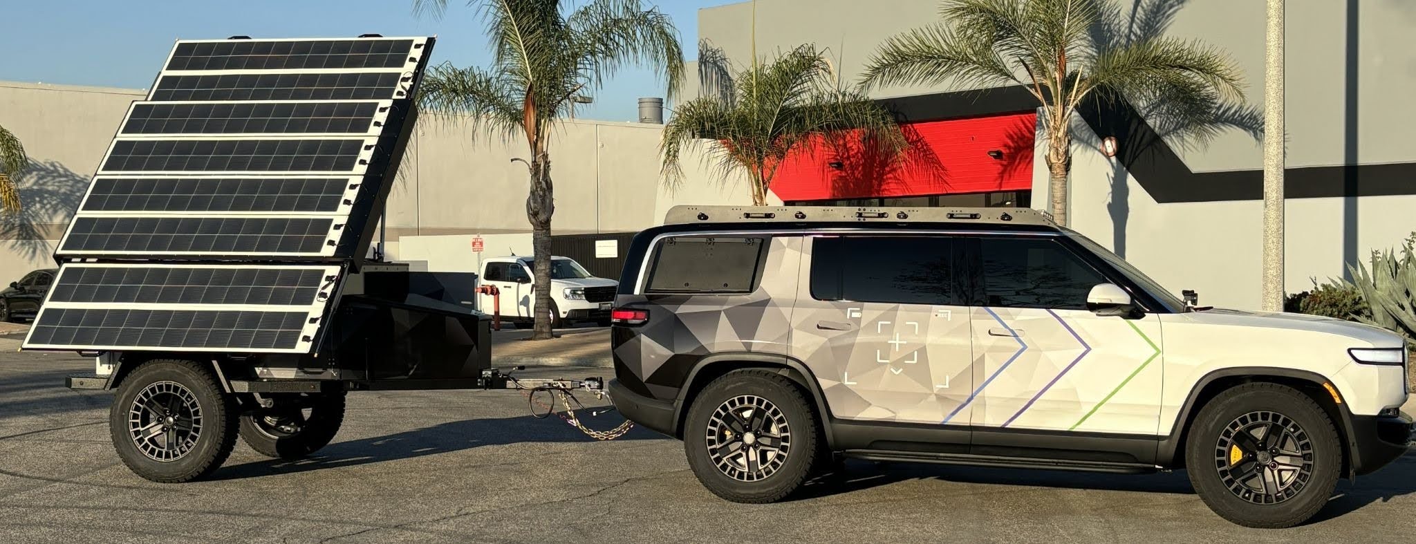
As part of an industry project, our client needed a Digital Imaging Technician (DIT) workstation and portable power station capable of supporting a film set’s power needs and EV charging in both local and remote locations. Our team retrofitted in-house designed and manufactured components to an all-electric SUV that fulfilled the needs of our client’s technicians. I contributed to the design and documentation, and supported the fabrication of the DIT’s internal workstation, external viewing hatch, and retractable server rack, ensuring proper ergonomics and overall function. The power station trailer frame houses four battery modules and supports a fully deployable and articulating solar array which can be precisely adjusted to harness maximum solar power. Half of the array's panels are always exposed, allowing for power generation during transportation or in confined spaces. The trailer can provide EV charging and support almost any power-demanding equipment. I was primarily responsible for the conceptual structure design, component sourcing, and hand calculations required for proper actuation of the array. I also assisted in the CAD modeling, documentation, and fabrication of the array’s structure and components.
Results
We received positive ergonomic and usability feedback on the DIT vehicle from a variety of users, specifically for the internal workstation and the external viewing hatch. All subsystems performed as expected and remained functional after transportation. Preliminary tests of the solar array proved that it articulated reliably with continued use, which validated the analytical hand calculations. The precise angle adjustability of the array also allowed for maximum solar power generation. Overall, the DIT vehicle and solar array concept proved successful and both have the opportunity for future feature enhancements.
Camp Stove Powered Water Heater
Summary
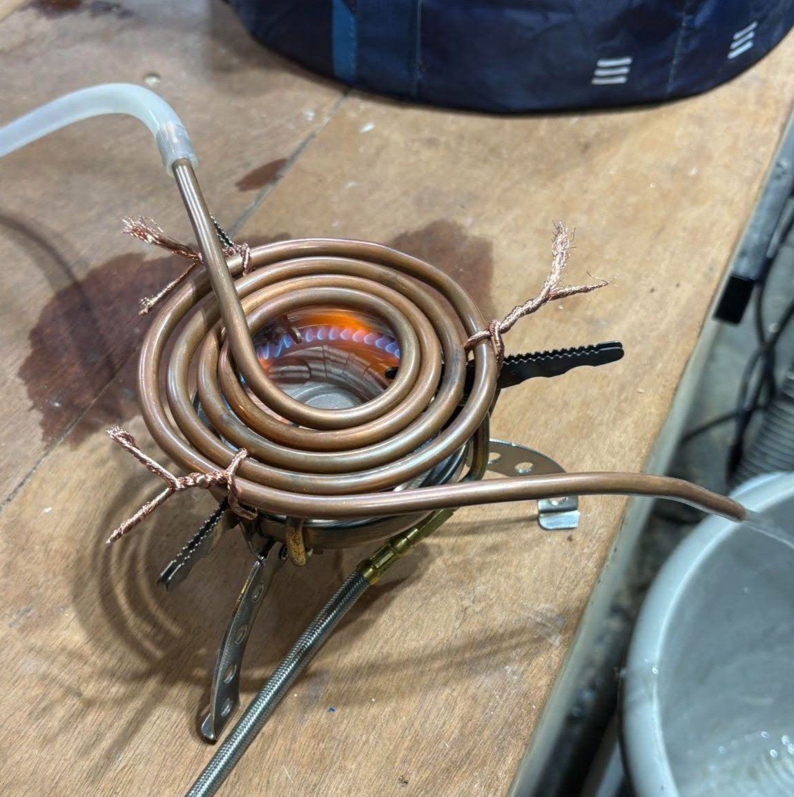
An initial prototype of a portable, isobutane camp-stove-powered water heater is shown in the project gallery. It utilizes primary and secondary heat exchangers that mimic the setup of a convection-based tankless water heater. Cold water first flows through the secondary heat exchanger, positioned above the primary, where it condenses water from the stove's exhaust gases onto copper coils, releasing latent heat to the cool water within. The water then passes through the primary heat exchanger, which provides most of the convective heat transfer. A CFD model was developed to simulate the heat transfer from the stove's flame to the copper tube and water. After validation against physical experimental testing, the model helped visualize heat transfer and optimize the coil size and orientation. It will also assist in improving overall efficiency when implementing design changes in the future.
Results
On average, the steady-state temperature difference (ΔT) between the water at the inlet and outlet was roughly 32° F at a flow rate of 1.13 L/min. Based on the expended energy of the camp stove, determined by the amount of fuel used over a given period of time, the efficiency of the device was calculated to be 70.5%.
Voice Controlled Wireless Shifter
Summary
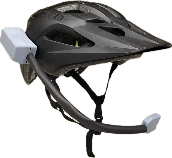
The goal of this project was to develop a speech recognition system for veterans with missing digits or numbness in their hands, enabling them to shift gears on their bikes. The device needed to recognize the wake word, “marvin”, as well as the keywords “up” and “down”, and communicate this information wirelessly to a wireless derailleur, which would shift the bike accordingly. The device utilized a neural decision processor trained on thousands of voice samples of the aforementioned keywords. A water-resistant, resin-printed enclosure housing the battery, microcontroller, and gooseneck-style microphone was attached to the rider's helmet. Upon identifying an up or down shift command, the device transmits a packet via BLE to the shifter, which executes a shift in the bike’s gears.
Results
After testing the device multiple times with four different users, the device's accuracy was found to be approximately 75%, with a peak of 85%. However, as each user used the device more, the accuracy improved, likely because they adjusted the way they spoke their commands to better match what the device was trained to recognize.
ADDITIONAL PROJECTS
Wobbler Engine
Summary
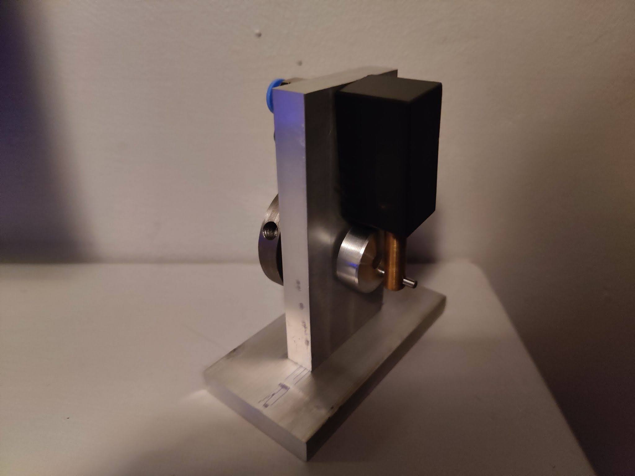
This wobbler engine was machined using both a manual lathe and mill. A variety of materials, including brass, aluminum, steel, and acetal, were used, each with unique workability properties that taught valuable machining methods.
Results
This particular engine was able to run continuously on only 1.25 psi of compressed air, the lowest pressure in the class. This is largely due to the precision of each machined component and their interaction with each other.
3D Printer to CNC Conversion
Summary
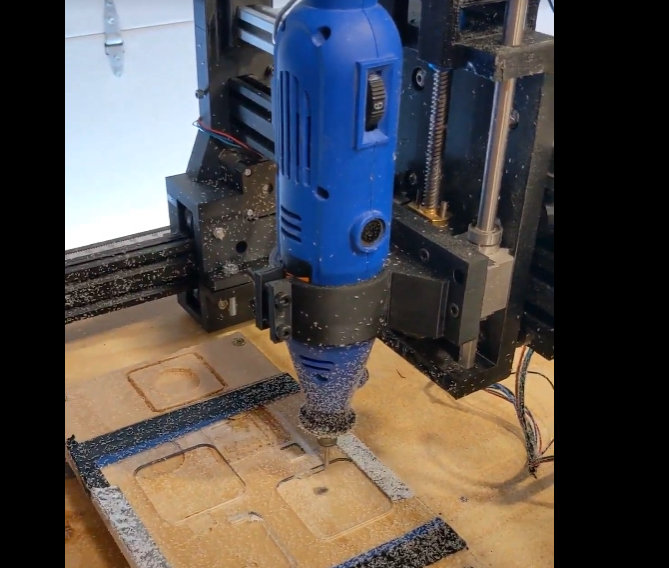
Using parts salvaged from an old 3D printer, I designed and constructed a CNC/laser cutting machine. The design was modeled in Fusion 360, and many of the structural components were 3D printed using PETG plastic. The project constraints were to create a robust and rigid machine capable of processing plastic and wood, as well as being able to laser engrave items with a diode laser that replaces the spindle.
Welded Coffee Table
Summary
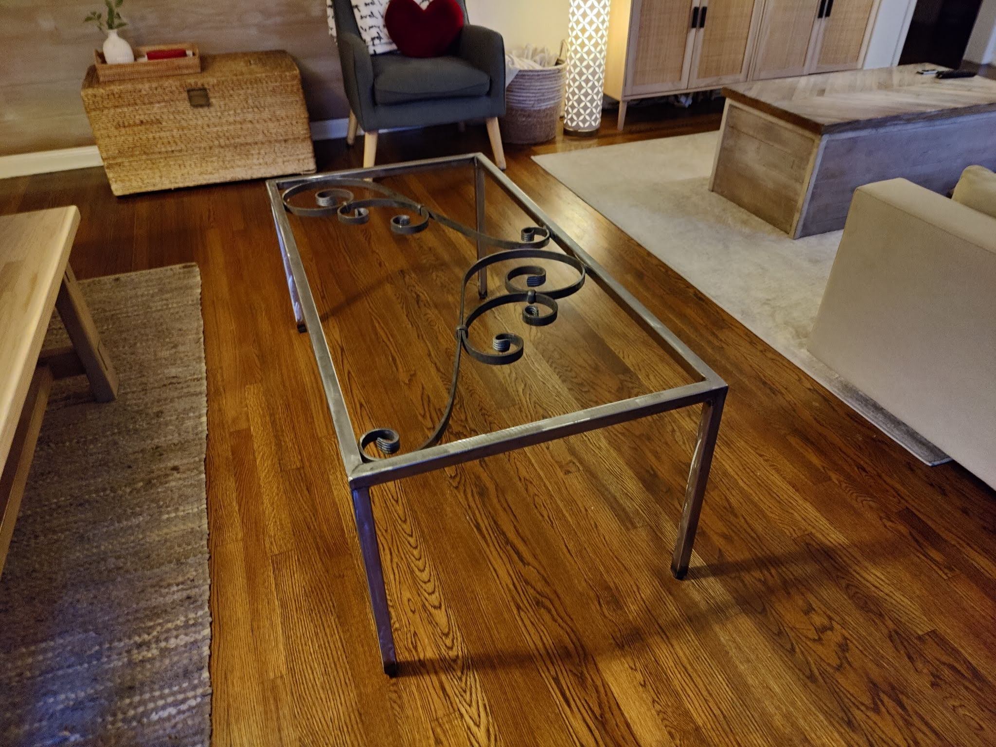
This was one of my first functional welding projects. I used square steel tubing for the frame of the coffee table and welded it together with a flux-core welder. Although this method of welding is not as clean and precise as MIG welding, I was able to create a functional table with a glass top (not shown here), decorative features, and leveling feet.
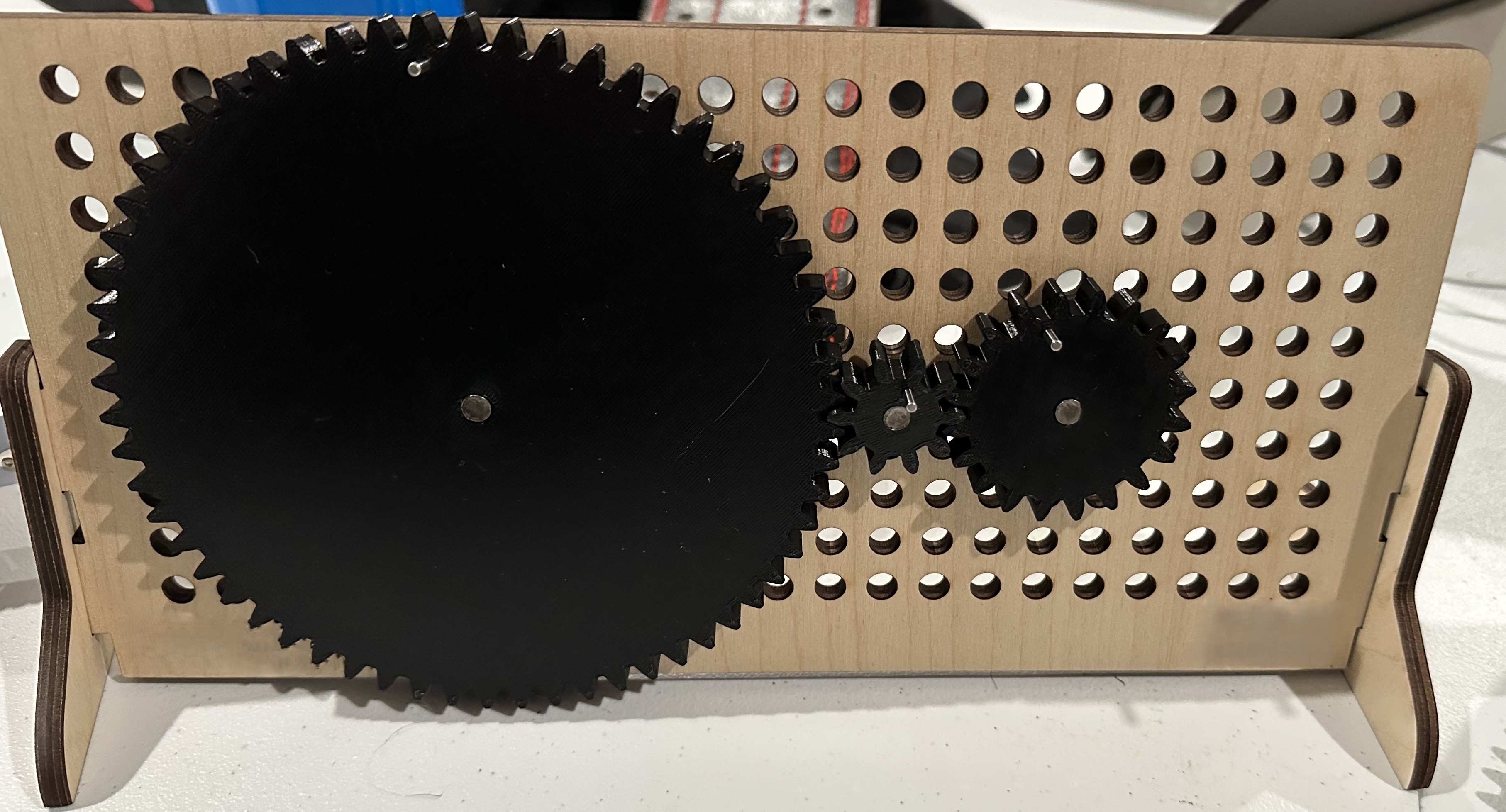
Gear Ratio Learning Tool
Summary
This was a demonstration tool designed and built to help students visually understand gear ratios. The gears were 3D printed and range from 1” to 6” in pitch diameter. Dowel pins were press-fit into the gears to slide into the holes on the laser-cut pegboard, allowing for various gear orientations.
Let's Build Something Together
Have an idea for something you want to engineer? Send me an inquiry and let's innovate together.